Further Reading:
An Outline of Structural Geology, 1976. Hobbs, Means & Williams p 73-104
Urai, Lister & Means 1986 Dynamic Recrystallisation of Minerals In : Mineral & Rock Deformation: Laboratory Studies Ed: Hobbs & Heard ,Geophysical Monograph 36.
Jessell & Lister 1990. A simulation of the temperature dependence of quartz fabrics. In: Deformation rheology and tectonics. Ed: Knipe & Rutter, Geol. Soc. London Special Publication No 54.
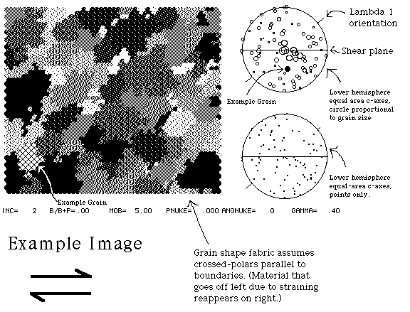
1) Computer simulations of crystallographic preferred orientation development.
The first part of the lab consists of a computer simulations of crystallographic
preferred orientation and grain shape foliation development in quartzites.

These simulations are calculated assuming that four deformation processes are involved, homogeneous simple shear, lattice rotations according to the Taylor-Bishop-Hill model, (which calculates the lattice rotations for a crystal based on its orientation, the applied deformation, and how easy it is for each slip system to be activated) grain boundary migration driven by dislocation density contrasts, and rotation recrystallisation at or near grain boundaries. The hidden assumptions are that the dislocation density in each grain is a function of how easily it deforms which is in turn a function of its orientation. Grains which require less stress to make them yield will have lower dislocation densities and will thus preferentially consume other grains, and will also more slowly develop subgrains by rotation recrystallisation.
The 3 simulations are set up to reflect increasing temperature, which will affect:
i) the Critical Resolved Shear Stress (CRSS) for different slip systems (ie how much stress resolved into a slip plane in the slip direction is needed to induce dislocation glide).
ii) the mobility of grain boundaries
iii) the rate of recovery
iv) the rate of rotation recrystallisation.
In order to simplify things we have assumed that the two dominant slip systems in quartz are basal and prism , although in fact other slip systems would probably operate as well. At low T (eg Greenschist facies deformation) basal slip is believed to have a lower CRSS than prism , whereas at higher T (eg granulite facies deformation) the situation is reversed. As a result two things happen: the patterns of lattice rotations vary (although not by all that much) and the grain orientations which have lowest dislocation densities will change. For the each simulations follow the grain size and c-axis orientation history of 4 grains from different parts of the stereographic projections (the same 4 grains each time) and contrast their relative fates.


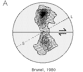
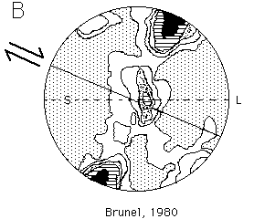
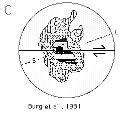
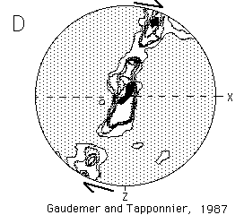
2) Natural CPOs in quartz
The following c-axis fabrics were all measured from regions thought
to have deformed predominantly in simple shear. These fabrics were
pulled from the literature by me, (based on my wish to find natural
analogues for the model results) so don't blame the authors for these comparisons,
and don't take them too seriously. Further details of these fabrics, and
the original reproductions of them, can be found in the references given.
Unfortunately they are plotted in two different orientations with respect
to the shear plane, so be careful. (S=foliation, L=lineation).
Which of the simulations above correlate with which natural patterns below?
 |
 |
 |
 |