contact Cover


3.1 Faulted dyke


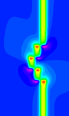
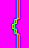
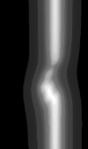
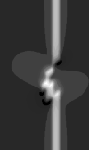
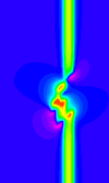
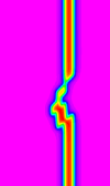
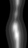
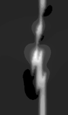
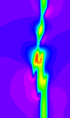
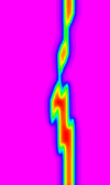
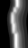
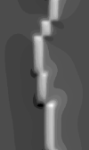
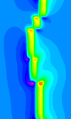
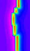
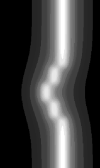
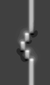
These models demonstrate the effects of varying the fault orientation with respect to a vertical dyke, and the ease with which the fault orientations cand displacements can be recognised.

All block diagrams are viewed from SW.

Click on the images to launch Noddy. A legend is provided at the end of this page.

Link
Block
Gravity
Magnetics
Magnetics
Magnetics at Pole
Magnetics at Pole 1VD
Faults at 90° to dyke

Open history with Noddy Open FracViewer Movie Open Geology VRML
View geology model

LOAD JPEG IMAGE

Open gravity with Noddy

LOAD JPEG IMAGE

Open magnetics with Noddy

LOAD JPEG IMAGE

Open magnetics at pole with Noddy

LOAD JPEG IMAGE

Open magnetics at pole 1VD with Noddy

LOAD JPEG IMAGE

LOAD JPEG IMAGE

In this model the apparent offsets are quite clear, although the results of section 2.2.5 show that the true offsets cannot actually be determined from this data.
Faults at 45° to dyke

Open history with Noddy Open FracViewer Movie Open Geology VRML
View geology model

LOAD JPEG IMAGE

Open gravity with Noddy

LOAD JPEG IMAGE

Open magnetics with Noddy

LOAD JPEG IMAGE

Open magnetics at pole with Noddy

LOAD JPEG IMAGE

Open magnetics at pole 1VD with Noddy

LOAD JPEG IMAGE

LOAD JPEG IMAGE

In this case the fault positions are still quite clear in the magnetic data
Faults at 20° to dyke

Open history with Noddy Open FracViewer Movie Open Geology VRML
View geology model

LOAD JPEG IMAGE

Open gravity with Noddy

LOAD JPEG IMAGE

Open magnetics with Noddy

LOAD JPEG IMAGE

Open magnetics at pole with Noddy

LOAD JPEG IMAGE

Open magnetics at pole 1VD with Noddy

LOAD JPEG IMAGE

LOAD JPEG IMAGE

In these images the fault positions and orientations start to become unclear, and the variations in dyke appearance along strike could be interpreted as thickness variations or rock property variations.
Faults at 60° to dyke, dipping at 60°

Open history with Noddy Open FracViewer Movie Open Geology VRML
View geology model

LOAD JPEG IMAGE

Open gravity with Noddy

LOAD JPEG IMAGE

Open magnetics with Noddy

LOAD JPEG IMAGE

Open magnetics at pole with Noddy

LOAD JPEG IMAGE

Open magnetics at pole 1VD with Noddy

LOAD JPEG IMAGE

LOAD JPEG IMAGE

This model re-emphasises the problem with reinterpreting true fault offsets from faults cutting a single marker horizon. (See section 2.2.5 for further examples.)

Key
Survey Parameters
Scales
dyke
r = 1k = 10-2
background
r = 0k = 0
image width
10,000 m
Inclination
-50° or -90°
Intensity
50,000 or 70,000 gamma
Flight height
80 m

max


min

max


min

All models created using
Noddy
Copyright © 1998-2002 AGCRC & Mark Jessell

WWW conversion by Ian Brayshaw